RF Power Detector
Introduction
This is a tutorial on how to build a Schottky diode power detector
The project files are available here
The Villard Cell
A Villard cell voltage-doubler circuit based on diodes. It rectifies an AC signal and produces a DC output proportional to the input amplitude. At RF frequencies, it’s implemented using Schottky diodes to maximize the sensitivity.
On the negative half-cycle, D1 conducts and charges C1, clamping the node. On the positive half-cycle, D2 conducts and the clamped voltage pumps C3 up. The result is a quasi-DC voltage at the output riding above ground.
Cascaded Villard Cells
The concept before may be extended to N cells by adding more branches at the RF input and adding the rectified voltage over the previous DC output. This improves the minimum detectable power, but its performance is poorer on high frequencies doe to the parasitics.
In the simulation below, a second Villard cell is stacked on top of the first. The intermediate node (Vout1_DC) feeds into a second clamping stage (D5, C6) and a second peak detector (D6, C7). The output now approaches ~1.6–1.7 V, roughly double the single-cell output, hence “voltage doubler.” The trade-off is that convergence is slower and the ripple at intermediate nodes is larger (visible in the zoom plot on the right — the green and red traces are messier than the single-cell case).
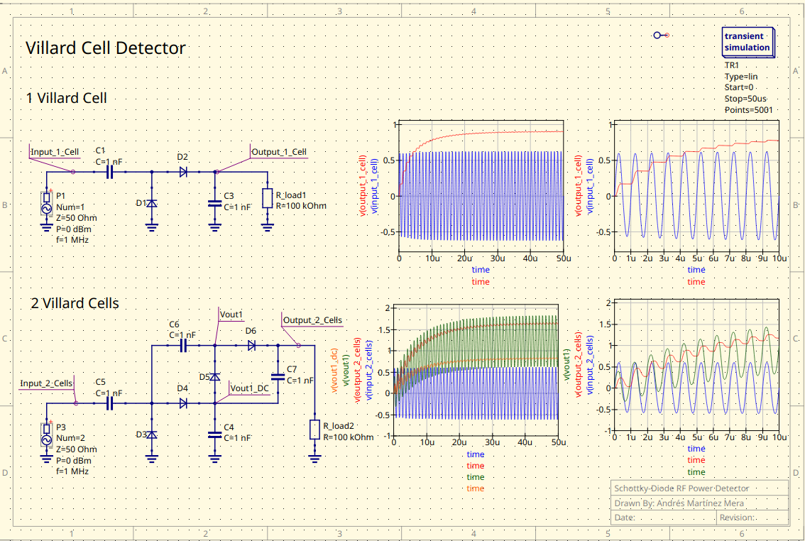
Schottky diode RF power detector